Appendix 1: Cable routing guide for tow chain
Specification proposal description:
To install high-flexibility cable, pay attention to the application requirements of high-frequency communication and high-frequency motion scenarios. In such scenarios, improper cable layout may cause problems, such as cable cover wear, internal conductor breakage, and camera packet loss.Based on the preceding situation, this section describes the basic cabling rules and precautions for sports cables to help you correctly install and use related products and improve the overall healthy operating life of the system. Improper installation will often lead to the cable in the tow chain often broken core, in the tow chain cable wiring installation precautions are as follows.
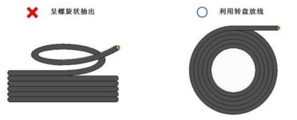
1.Do not twist the cable
Do not twist the tow chain cable when removing it from the box. Do not unwrap a cable from one end of a cable reel or cable tray. Instead, you should roll the drum or cable tray to unfold the cable first, and you can roll or hang the cable when not in use.
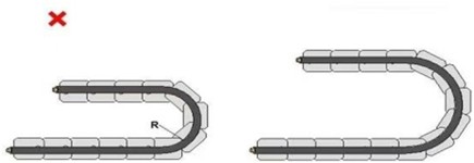
2.Keep the cable bending radius as large as possible
The bending radius of the cable refers to the maximum degree that the cable can withstand when it is working normally. The outer diameter is 4mm, then the bending radius R should be greater than (dynamic/static): 80mm/40mm.
3.Tension distribution and fixing method in tow chain.
If the drag chain cable is stretched by tension during wiring, it will cause friction on the inner wall of the drag chain and thus sheath wear. When wiring is too loose, it will also cause friction on the inner wall of the drag chain, resulting in jacket wear and entanglement of the cable inside the drag chain.
The moving part of the cable cannot be fixed. If it is fixed, the bending stress cannot be dispersed and absorbed, resulting in stress concentration at the fixed position. Secure the cable at both ends of the tow chain. The distance between the moving point of the cable and the end of the tow chain should be 80 mm to 120mm.
Cable tensile strength (long/short term): 150N/300N; Flattening strength (long/short term) /100mm: 500N/1000N.
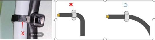
①Choose the length and bending angle of the cable appropriately to maintain the freedom of the bending part of the cable. If there is a cover (cover) on the top of the camera or a fixed cover (cover) around the camera, do not touch the fixed cover (cover) with the cable to prevent friction between the cable and the cover when the camera slides.

②A combination of multiple cables, especially with different outer diameters, while maintaining the freedom of the curved part of the cable.

③Do not bend excessively near the binding part and do not tighten the cable directly to deform the cable!
④Use a casing or shell to support the U3 connector.

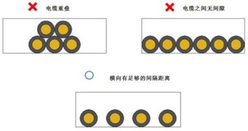
4.Prevent interference between cables.
Select a tow chain that can ensure the cable spacing. When horizontal wiring is implemented in the tow chain, the gap between the cables should be at least 10% of the cable diameter (0.4mm), so that mutual interference between the tow chain cables can be prevented during wiring.
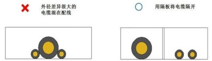
5.Mixed distribution of cables with large outside diameters.
When cables with large outer diameters are mixed, a partition is required to separate the cables to prevent the thin cables from being compressed by the thick cables and the cables are easily broken.
6.Weak wires and strong wires should be separated from each other.
Weak wire and strong wire should be wired separately, the distance is controlled above 50cm, and the aluminum foil outside the weak wire is isolated for protection (the camera optical fiber wire is a weak wire, 110V, 220V and 380V industrial electricity is a strong electricity), especially the servo motor power supply line should not be bundled with the camera wire.

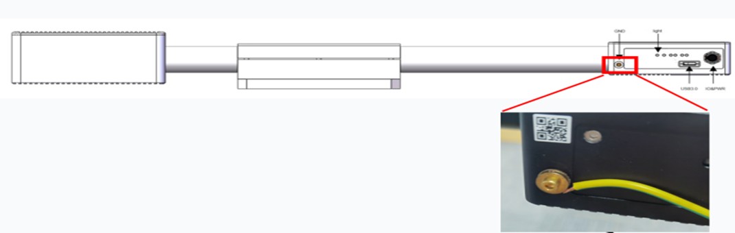
7.Check grounding and leakage.
The equipment (industrial computer, camera, etc.) is well grounded, and the equipment is as far as possible with three-plug power supply, the power cord wiring is standardized and the wiring is correct, and the socket leakage detector can be used to check.MP camera grounding legend:
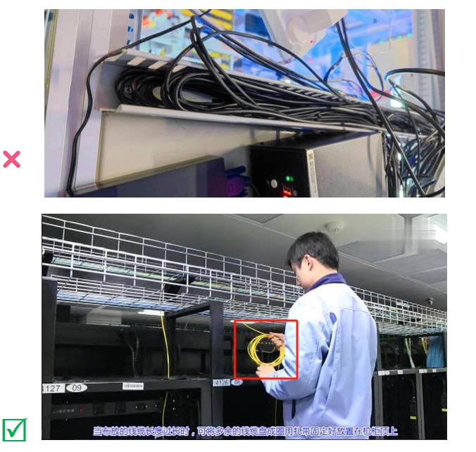
8.Place the remaining lines.
After the cables are routed, if the length of the cables is too long, coil the redundant cables into circles, secure them with cable ties, and place them on the cabinet (do not bind the cable ties too tightly to distort the cables). Do not fold the excess cable in half and place it in the cable slot!
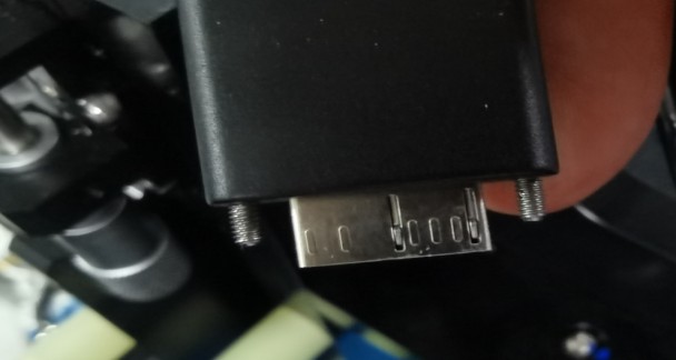
9.Fasten the screws on the cables.
After the cable is inserted into the camera, after the camera is enumerated by the computer, lock the screws with the camera. When locking the screws on both sides of the cable, enter one third the screws on one side first, and then tighten the screws on the other side. Step by step, do not tighten one screw first and then tighten the other side to avoid deformation of the pin in the connector!