Connectivity and Power Supply
Power Adapter Details
- Input: 100-240VAC, 50/60Hz, 1.4A
- Output: 24V—5.0A, 120W MAX
Using power adapters with different voltage and current specifications may damage the device or impair projection. For dimensions of the power adapter and applicable camera models , see: Power Adapter and applicable camera models.
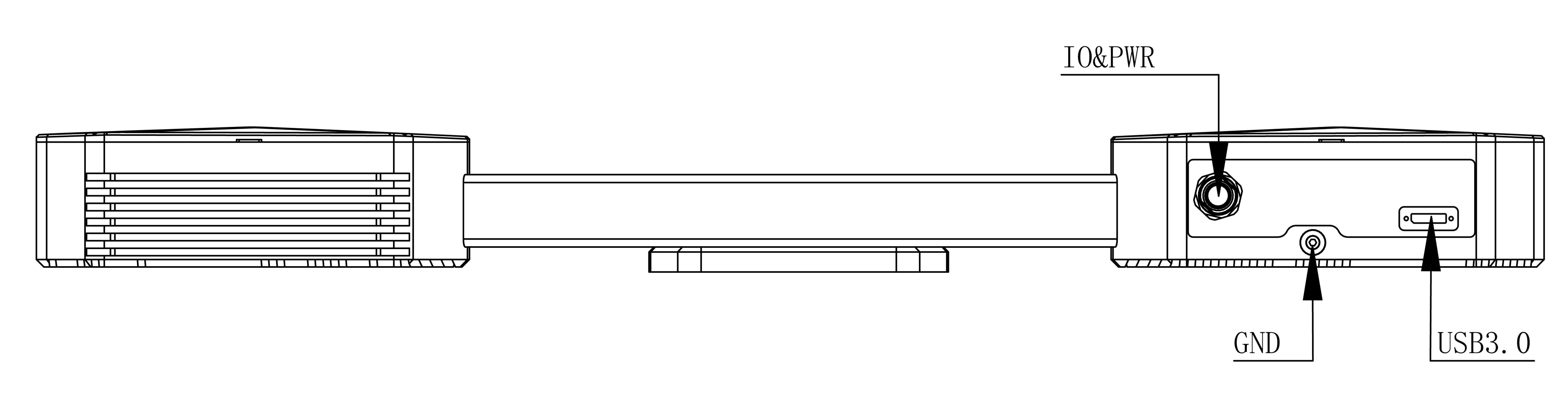
Control Cable Wiring Details
The camera provides external hard trigger IO ports, offering corresponding IO control cables and wiring instructions. For detailed information, refer to IO Control Cable Dimensions.
USB High-Speed Data Cable
A standard USB interface enables camera connection control and data transfer. Detailed information about the provided USB high-speed data cable can be found at USB High-Speed Data Cable Details.
Device Status
Device status (DeviceState) includes the following five states:
- Disconnected: No communication operations can be performed.
- Under Init: Register values can be set, but the device will not perform any operations.
- Standby: The device is idle and ready for new captures.
- Under Exposure: The device is exposing; movement of the object being measured or vibrations should be avoided as they may increase the error in the 3D point cloud.
- Under Transfer: The device has completed exposure and is transmitting the 3D point cloud to the PC. At this time, the object being measured can be moved to shorten the cycle time.
Device status can be retrieved either by polling or via callback functions. Callback retrieval is recommended to avoid frequent polling. In addition to software interfaces, the Device indicator light also reflects the device's state:
- PWR (Power) : Yellow-Green Solid Light(Indicates normal power supply status)
- HW (Hardware) : Yellow-Green Solid Light(Indicates all hardware components functioning properly)
- SW (Software):Green Blinking Light(Indicates successful software communication)
①* The camera's power & IO integrated 17-pin interface includes two Input holes and two Output holes. When connecting, make sure the direction of the power cord plug matches the interface.
Reset
When a product malfunction requires a reset, the following table lists the scenarios:
| No. | Issue | Possible Causes | Solutions |
|---|---|---|---|
| 1 | Camera cannot connect to PC | 1. USB not securely connected; 2. Driver not correctly installed | 1. Reinsert the USB cable, power cycle the camera; 2. Run the installation batch |
| 2 | USB displayed as USB2.0 | USB not securely connected, USB driver poorly installed, or connected to a USB2.0 port | Confirm USB3.0 driver installation, reconnect and power cycle the camera |
| 3 | Camera cannot take pictures | External interference or internal malfunction | Stay away from sources of interference or shield them, then restart camera power |
Important Notices:
- This product must be installed by a professional. Always follow the operation guidelines to avoid injuries and safety issues.
- Do not attempt to open or repair the device yourself; incorrect handling can cause permanent damage.
- Do not move or disassemble device parts after installation.
- Read the relevant documentation carefully before testing or operating.
- Ensure the installation bracket is free from severe vibrations.
- Maintain consistent environmental temperature and humidity to ensure testing consistency.
- Use professional tools to clean the lenses to avoid damage.
- Prolonged exposure to high-intensity blue light emitted by the projector may damage your eyes.